The FS Box LIGHT is installed as a connecting element in cast-in-situ concrete, semi-precast or in full precast components. The product consists of a sturdy sheet steel box in which the fold-out, flexible wire rope connection loops are located. The box is designed to transmit forces from static and quasi-static loads.
Time saving - flexible wire rope loops automatically spring to the target position
Safety - no rigid bars sticking out of the concrete
Easy installation – any arrangement
European Technical Assessment (ETA)
High performance application-orientated load capacities
Optimum profile for optimum connection
Low mortar consumption
Free dimensioning software
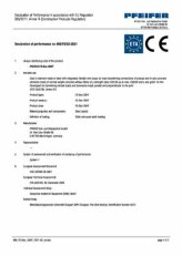
CE marking
Product Info
Application areas
Precast wall (load bearing)
Precast wall (non-load bearing/structural)
Double wall/semi-precast wall
Column
Installation type
Wire rope loop boxes for the load bearing connection of different precast wall elements: Precast element – in-situ concrete/semi-precast concrete; in-situ concrete- in-situ concrete/semi-precast, semi-cast element – semi-precast element
The wire rope loops of the FS Box® LIGHT engage in the in-situ concrete area of a wall when installed and, in combination with the transverse bar installed by the customer, guarantee a load bearing connection of the elements
Function
When installed, the wire rope loops of the FS Box LIGHT engage in the in-situ concrete area and, in combination with the cross bar installed by the customer, ensure a force-locked connection of the elements.
The joint is also filled in accordance with approval, with the in-situ concrete.
Erection of cable structure
Precast factory: Nailing/hot-gluing to formwork, additional reinforcement according to approval, concreting and compaction - finished.
Construction site: Pull off tape, unfold wire rope loops, thread in cross bar, concreting and compacting - finished.
More detailed information on installation can be found in the corresponding product brochure. This can be found under the "Downloads" tab.
Design / Engineering
Possible loads
The box is installed as a connecting element and is designed to transmit forces from static and quasi-static loads.
Shear loads running parallel and perpendicular to the joint as well as tensile loads are regulated by the building authorities.
Interaction of influences from all three directions is permitted.
Calculation
The admissible design resistance values are shown in table form in the associated product brochure.
For quick planning and dimensioning, the user has free dimensioning tables available under the "Downloads" tab.
Videos
Installation instructions Fastening for push-pull props MoFi® / FS Box® for in-situ concrete
PFEIFER Cables y Equipos de Elevación S.L.
Avda. de los Pirineos, 25 – Nave 20, San Sebastián de los Reyes
ES-28703 Madrid
Tel. +34 630 336-445
Fax +34 91 659-3139
E-Mail cconejero@pfeifer.es
Web www.pfeifer.es
Sales subsidiary
Poland
PFEIFER Polska Sp. z o. o.
ul. Wrocławska 68
55-330 Krępice k. Wrocławia
Tel. +48 71 30 23 300
E-Mail info@pfeifer.pl
Web www.pfeifer.pl
Office
Czech Republic
PohlCon Ceská republika s.r.o.
Bavorská 856/14
CZ-15500 Praha 5
Tel. +420 272 700 701
Fax +420 272 700 704
E-Mail info@jpcz.cz
Web www.pohlcon.cz
We use cookies to optimise our web page for you. By continuing to use the web page you agree to the use of cookies. Further information about cookies can be found in our data protection declaration.
Required cookies
Required cookies are mandatory for the basic functions of the website. Without these cookies, you will unfortunately not be able to use our website.
These cookies are always set when you use the website. No personal data is collected or stored.
Functional cookies
These cookies allow us to analyze website usage so that we can measure and improve its performance.
No personal data is collected or stored.